 |


 |


Concept Analyst uses a technique called the Boundary Element Method, or BEM, to compute the stresses and dispacements in an object subjected to some loading. The reason for this choice will become apparent as we go through this page, but for the moment let us just say it is similar to the more widespread Finite Element Method, or FEM. If you are involved in computational stress analysis, you will know that the FEM forms the basis for most commercial systems, including codes like ANSYS, NASTRAN, ABAQUS, etc. The BEM is also used in commercial systems like BEASY, and some other codes for electromagnetic and acoustic design.
Here are the similarities between the FEM and the BEM
- they both work by dividing the geometry into 'elements'
- they both work by placing 'node' points on elements and using these to approximate the geometry, displacement, stress, etc. over the element
- they both work by describing the stress/displacement behaviour of the object mathematically as a set of simultaneous equations in matrix form
- they both give you deformed geometry plots, contour plots of stresses over the object, etc.
So ... they're very similar really. Now let's look at the differences, and here we will assume we are going to do an analysis of a 2D object in, say, plane stress:
- the FEM requires the whole area of the object to be split into elements of area (triangles and quadrilaterals) but the BEM requires only the perimeter of the object to be split into line elements. This makes the BEM really easy, and especially so when you want to make a change to a model.
- the FEM is more versatile, so if you are using materials with non-linear stress-strain curves, for example, then Concept Analyst is not going to be too helpful.
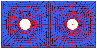
- The different elements are shown in the pictures below, which show a finite element mesh (upper) and a boundary element mesh (lower) of a plate containing two holes.


Most text books on the BEM are very mathematical; some might say they are unnecessarily mathematical. They are written to be a complete guide to the method but, valuable though they are to people like us that write BEM software, they're not very helpful to the engineering community that wants to use the method and wants to know enough about it to make sure they use it safely. It is all too easy to get lost in the rather off-putting equations without seeing the main points.
So here is a technical overview of the method, specifically for stress analysis; there are similar developments for other applications.
The method is based on the concept of influence. A point force at some position in an infinitely large piece of material has an influence on the stress and displacement at every other point. Fortunately we have equations developed by Kelvin in the 19th century that allow us to calculate these influences - they are just functions of the geometry of the two points and material properties. Using these expressions, we calculate the influence of a force at every point on the perimeter on the displacement and stress at every other point on the perimeter, and build these into a large set of simultaneous equations that will be true for every possible load case.
But our analysis isn't confined to infinitely large materials. It is by specifying boundary conditions that we relate those influence expressions to the real design geometry being analysed.
If we apply our boundary conditions for the particular load case we are considering, then we can solve the simultaneous equations to find the displacements and stresses around the perimeter of the object.
To find the displacements and stresses at any point internal to the object, we have to evaluate an integral over the perimeter, which is relatively straightforward once we have the solution on the perimeter. Internal point solutions are accurate and not a clumsy interpolation from results at the boundary.
As you have probably guessed, the description in this section is, in truth, a gross oversimplification of the method, but it does provide a simple overview of the procedure. If you want more detail, just carry on reading.
It is possible to derive the Boundary Integral Equation (BIE), on which the method is based, in various different ways. Many authors start from a weighted residual statement, which I suppose is OK if you are familiar with this type of numerical method. On the other hand, if (like me) you are approaching this from a background in engineering rather than in mathematics, you will probably prefer my approach which starts from the reciprocal theorem. This, at least, has its roots in the mechanical behaviour of structures.
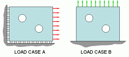
There are different ways of expressing the reciprocal theorem, but the one we will use is this. Consider an object subjected to two load cases; we will call them A and B. Here they are:

The reciprocal theorem is a statement of equivalence of work. It states that the work done by the forces in load case A on the displacements in load case B is equal to the work done by the forces in load case B on the displacements in load case A. Since work = force x displacement, we can write (not very scientifically at the moment)
You can easily verify this by considering, for example, a cantilever beam under a couple of loadings, e.g. point load and u.d.l.
Being a little more scientific about the statement now, we will say that in load case A the forces are made up of boundary tractions t and body forces b, and the displacements we will denote u. For load case B we will use the same notation but use an asterisk, giving t*, b* and u*. If you are unfamiliar with tractions they are rather like stresses - a traction perpendicular to a surface will be an applied pressure (or suction), and a traction tangential to a surface will be an applied shear stress. Tractions in other directions become a little more complicated, and I'm not going to define them here, but a useful property is that (unlike stresses) tractions can be resolved into components and, conversely, combined into a resultant.
Since tractions are applied only at the boundary (perimeter) of the object, work is done only over the boundary, S. Body forces (e.g. gravitational or thermal loads) act throughout the volume, V. So we can sum, or integrate, the work done by writing the reciprocal theorem as
 | .............(2) |
|---|
Notice how the traction terms are only considered on the surface and the body forces are considered through the volume.
We now define our load cases
Load case A is the real load case we are trying to solve.
Load case B is simply a concentrated point force at some location 'p' in the object.
Because we've chosen a point force as the load case B, we can use the Kelvin 'fundamental solution' to compute u* and t* at any location 'Q'. As we have already seen, these are just functions of material properties and geometry that are easily calculated for any pair of points 'p' and 'Q'. If you are interested, they are as follows for 2D (there are similar expressions for 3D cases):
 | .............(3) |
|---|
 | .............(4) |
|---|
where i and j represent the directions of the displacement or traction component at 'Q' and the force component at 'p', r is the distance from the point 'p' to 'Q', μ and ν are the shear modulus and Poisson's ratio of the material, and δ is the Kronecker delta, which takes the value 1 if i = j, otherwise it is zero. At this stage it is not important to understand what all of these terms mean; the important thing is that for any pair of points 'p' and 'Q' we know all the terms on the right hand side of these expressions and can therefore evaluate u* and t* quickly in a code like Concept Analyst.
As well as knowing these fundamental solutions, the particular choice we have made for the load case B is very helpful in that it may be shown that the volume integral on the left hand side of equation (2) reduces to a simple form
 | .............(5) |
|---|
(If you are interested in why this is, it is because the point force is so concentrated it is expressed as something called a Dirac delta function, and we can use the properties of this function.) If we also assume the body forces in the real load case, b, to be zero, we can reduce equation (2) to a much simpler form
 | .............(6) |
|---|
Both volume integrals have been removed (and this is why we no longer need finite elements). The only thing that remains in this expression that relates to a point off the boundary is the first term 'u(p)', which means the displacement (in the real load case) at point 'p'.
BUT ... when we defined what load case B was going to be (above) we said it was a point force at 'p'. But we did not say where 'p' was. Let's now take it to the boundary. So the whole equation now refers only to boundary terms. In taking 'p' to the boundary, we introduce a multiplier c(p) for reasons I'm not going to go into here. But it is not a difficulty because c(p) takes the value of 0.5 if 'p' is on a smooth boundary, and (more generally) on any piece of boundary takes the value θ/2π, where θ is the angle subtended by the material at 'p'.
We therefore have the final form of the equation, which we shall call the Boundary Integral Equation.
 | .............(7) |
|---|
This equation lies at the heart of the BEM. You can see the reciprocal nature of the displacements and tractions that lies within this equation. Similar equations show similar reciprocity between, say, temperature and heat flux density in a thermal analysis, or between pressure and velocity in an acoustic analysis, or between voltage and current density in electrostatics.
In the early days, people used to try to solve the boundary integral equation analytically. This is practical only for the very simplest problems and not very useful for real engineering purposes. The problem comes with the difficulty of evaluating the integrals in equation (7).
Yes, we have said that the terms u* and t* can be easily calculated for any pair of points, but it is an altogether different matter integrating these functions over the boundary, S, as is required in the equation. The first step to make in overcoming this is to look at numerical integration. This is classically done when analytical integration becomes too difficult. You will probably remember the trapezoidal rule, and maybe Simpson's rule, for numerical integration. These methods involve evaluating the function to be integrated (the integrand) at a set of discrete points and then multiplying these by weighting factors and summing to reach the value of the integral. The method most BEM (and FEM, for that matter) programs use is called Gauss-Legendre quadrature, which is different but works like the trapezoidal rule and Simpson's rule in practice.
The key to accurate numerical integration is to be sure to divide the region of integration up into a sufficient number of sufficiently small divisions. So to integrate equation (7) we split the boundary, S, into small divisions, Se, e = 1,2,3,...; these are the boundary elements. We integrate numerically over each element and sum all these element integrals to find the total.
 | .............(8) |
|---|
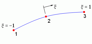
Like finite elements, boundary elements have nodes. Here is a quadratic line element with three nodes, which is the default used by Concept Analyst. There is a local coordinate system, ξ, defined over the element in the same way as finite elements.

The nodes form a crucial role in the analysis. They are discrete points at which we are going to assign values of displacement and stress. Three of them are shown in the above image of the quadratic line element. The displacement and stress at any other point on the element can then be found by interpolating from the nodes. This is done through the use of shape functions; just the same as in the FEM, in fact.
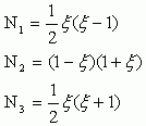
The quadratic element shown above will have a set of shape functions, in the local coordinate x, as follows:
 | .............(9) |
|---|
so that the displacement, u, at any point on the element will be found by interpolation using
 | .............(10) |
|---|
where NT is the transpose of a vector containing the shape functions in equation (9), and u is a vector containing the values of the displacement at the three nodes. We can apply this equation (10) to find the displacement in the x-direction or the y-direction. Similarly the traction, t, at any point is given by
 | .............(11) |
|---|
Replacing the dispalcement, u, and traction, t, in equation (8) by the interpolated forms (10) and (11) is an important step. We need to find the value of the integrals in (7) to be able to solve the problem. The difficulty with this is that we can't evaluate the integrals until we know u and t; these are, of course, what we seek as the solution to the problem so we don't know them yet. However we can move forward by replacing u and t with the interpolated forms in (10) and (11), so we have
 | .............(12) |
|---|
where the J terms are called the Jacobian and are there because we have changed the variable of integration to the local coordinate ξ (it's pretty easy, because for a flat element or a circular arc element, J is half the element length). Now recognise that the vector u, although we don't know it yet, contains only the values of displacement at the nodes and so does not vary over the length of the element. It may therefore be treated as a constant and removed from the integral. If we do this also for the traction vector t we write
 | .............(13) |
|---|
For any position 'p', and for every element on the boundary, then, everything inside the integrals is known and can be evaluated at any point on the element. So we can use our Gauss-Legendre quadrature (remember - a bit like the trapezium rule) to compute the values of our boundary integrals over the elements.
We can start by placing the point 'p' at node 1 and apply a force in the x-direction. Integrating over every element, equation (13) then yields an expression
 | .............(14) |
|---|
where the h terms arise from the integrals of the t* terms and the g terms arise from the u* integrals. The term c(1) and all h and g terms are known. In fact, the equation (14) as shown is simplified because I haven't shown all the different directional components. But it does show the general idea that by evaluating all our integrals, considering 'p' at node 1, we can write an expression for the displacement at node 1 as a linear combination of the x- and y-displacements and x- and y-traction at all the nodes. So equation (14) provides us with an expression in which the unknowns are the displacement and traction components at each node. Obviously since this single equation contains many unknowns we cannot solve it. However, a similar expression can be found by placing the force in the y-direction at node 1. We now place the point 'p' at node 2, and then node 3, etc., repeating the integration step and generating in the end a large number of simultaneous equations of the form of equation (14) with different h and g terms arising from the different integrations. Let's write the simultaneous equations in matrix form.
where H is a square matrix that contains the h terms, and G is a matrix (actually it is rectangular for reasons I'm not going to go into here) that contains the g terms. The vectors u and t contain the, as yet unknown, displacements and tractions in each direction at each node on the boundary.
At this point I should point out that the integration is more difficult than in the FEM, because at some point you have to evaluate the integrals over an element containing the node being considered as 'p'. In cases like this, because of the form of the fundamental solutions u* and t* in equations (3) and (4), we have to integrate functions that go to infinity at one point in the element. At first sight, you would think that this would give us an infinite value for the integral, but in fact it doesn't. I'm not going to describe how, but it is possible to evaluate these 'singular integrals'.
If we have N nodes, there will be 2N equations in the system represented by equation (15), i.e. there will be 2N rows in the matrices H and G. Assuming for simplification now that the G matrix is square so vectors u and t each contain 2N terms, you should see that (15) is a set of 2N equations but with 4N unknowns. This means it cannot be solved as yet. (If you're interested, this is analogous to the fact that in the FEM the stiffness matrix is singular, and also cannot be solved, until the boundary conditions are applied to reduce the system to the 'active' part of the matrix).
Like in the FEM, the problem is quickly resolved by applying the boundary conditions specific to the problem being solved. The easy way to do this is to require that the user prescribes, for each row in (15), either the traction or the displacement so that it no longer remains unknown. In other words, we have to tell Concept Analyst either the x-direction displacement or the x-direction traction at all nodes. Same for the y-direction. It is not a problem because if you do not specify a boundary condition on an edge, it will be taken as a free surface, for which we have zero traction in both directions. This reduces the number of unknowns to 2N allowing the system to be solved.
But there is a bit of work to do first. The vectors u and t both contain some values we just prescribed as boundary conditions and some values (displacements and tractions) that remain unknown.
The first step in the solution is to shuffle the columns of H and G to bring all the terms that still remain unknown to the left hand side, taking all the terms specified as boundary conditions to the right hand side, giving
in which A and B are matrices containing columns of H and G, x is a vector of unknowns (made up of some displacements and some tractions) and y is a vector of known displacements and tractions that have just been specified as boundary conditions. Since we know the matrix B and the vector y, we can multiply out the right hand side to leave a vector b,
This can be solved in a variety of ways. The fact that A is unsymmetric and fully populated restricts the choice of solvers rather more than for FEM systems, but there are some well established direct solvers like Gauss Elimination and iterative solvers like GMRES that can readily be applied to this system. So we find x, which contains all the unknown displacements and tractions at the nodes. These, in combination with the presecribed boundary conditions and with the interpolation equations (10) and (11), give us the displacements and tractions at any point on the boundary.
The stresses can fairly easily be obtained from the traction and displacement values.
So we now know the solution around the boundary. From here, it is a similar process to go about finding the stresses and displacements at any point of our choosing inside the material, i.e. not on the boundary. To do this we go all the way back to equation (6), very similar to the boundary integral equation but before we placed the point 'p' on the boundary. Here, then, 'p' can be anywhere inside the material.
When we developed equation (6) we did not know the solution around the boundary. But now we do. For any internal point 'p', we can now evaluate the integrals in (6) straight away to find u(p). this is the displacement at the internal point.
Stresses at the internal point 'p' can be found by a similar integral based on the derivative of equation (6).
So the results internally are true integrated solutions, and not some crude interpolation. These are the results that Concept Analyst uses to generate its contour plots of results and its internal line plots.
One of the principal features of Concept Analyst is the ability to perform a re-analysis. This is an analysis of a slightly different problem to one that has already been analysed. The challenge is to make the re-analysis as fast as possible. This is where the advantage of the BEM is found over the FEM. It is easy, fast and reliable to make an automatic change to the 'mesh'. For example when a hole is moved, it is only the elements on the hole that move. All other nodes and elements remain unchanged, and the vast majority of the system matrix, A, can be reused from the original analysis. The same is true for most types of geometric change, e.g. dragging a vertex of the polygon describing the object to a new position, resizing a fillet, resizing a hole, deforming a spline.
In addition to the greatly reduced number of computations required to build the system matrix, A, it is also faster to solve the system. Concept Analyst uses an iterative solver for most re-analysis runs, and uses as the first 'guess' in the iteration the solution to the previous design step. For moderate magnitude changes in geometry this can provide a very good starting point for the iteration. These changes require the total number of nodes to be unchanged so that the system matrix remains the same size. It is possible that this could be extended, and a first guess taken from some interpolated mapping from the old vector b to the new vector.
For the case in which a new hole is added to the geometry, the size of the system does increase, but in a special way. The original system matrix remains as the top left hand corner of the new system matrix. In this case, a direct solver is used with Gauss elimination so that the reduced form of the matrix can be re-used. This greatly speeds the calculation.